AstroNav | Flight Controller
A practical overview of the custom PCB at the centre of AstroNav and the design ideas recorded in the original build page.
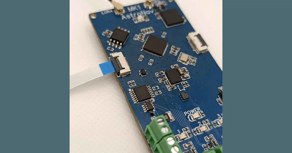
The flight controller is the electronic centre of AstroNav. I designed the PCB to collect sensor data, keep a flight log and communicate with the handheld base station while fitting inside a model rocket.
This page describes the design recorded in the original 2024 article. It is an archived hardware overview, not a current product specification.
RP2040 at the centre
The board uses an RP2040 microcontroller—the same family used by the Raspberry Pi Pico. Its two Cortex-M0+ cores and maker-friendly software ecosystem gave me enough room to experiment with real-time calculations, sensors and radio communication.
Sensors and flight states
The archived design describes a barometric pressure sensor plus an inertial measurement unit with an accelerometer and gyroscope. Together, those sensors were intended to support altitude estimates, motion measurements and detection of events such as launch, apogee and landing.
Power, logging and telemetry
Rocket electronics have to deal with battery power, electrical noise, vibration and sudden loads. The PCB therefore included power regulation and filtering, along with onboard storage using flash or microSD depending on the revision.
Wireless telemetry sent data to the base station during a flight. Local logging remained important because a radio link can never be assumed to be perfect.
Expansion and ignition experiments
Headers and connectors made it possible to attach extra sensors, cameras or other modules. Some revisions also experimented with e-match control. Flight 1 showed why that circuit—and the launch process around it—needed careful redesign and proper safety controls.
The firmware and PCB continued to evolve after this article. That is part of the reason I document the project: every revision captures what I understood at that point in the build.